
***************************************************************************************************************************************************
ASIAN INDENTATION HARDNESS TESTER FOR PU – FOAM
The feel of softness of any flexible foam is quantitatively defined by its indentation hardness. Indentation hardness of foam is determined by pressing a circular indentor at a specified speed against a block of foam and finding the force needed to compress it to a specified percentage of its initial thickness.
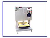
The “ASIAN” Indentation Hardness Tester for polyurethane foam consists of a circular indentor which can be pressed against the foam block under test, a motorized arrangement to move the indentor, and a load indicating arrangement to indicate the load being exerted by the indentor on the foam block at any instant.
The indentor is in shape of a circular disc and is mounted on a self-aligning ball bearing to ensure that it sits parallel to the surface of the test specimen. It is mounted at the lower end of a screw, which can be raised or lowered at a specified speed with the help of a motor and worm reduction gearbox. An arrangement to stop the motor at extreme ends of travel of the indentor is provided.
The downwards movement of the indentor is measured with the help of a pre-set type digital displacement meter, which can be set at any desired value to stop the motor automatically at a desired displacement. A linear scale is provided to indicate the gap between the bottom face of the indentor and the loading platform. The indentor can also be moved by hand to apply the initial load.
The load platform is made of cast aluminium and has a large number of holes arranged in a grid for rapid escape of air during compression. It is mounted on shear beam type load cell. A digital load indicator is provided to indicate the load acting on the test specimen.
The equipment is finished in blue metallic painting and bright chrome / zinc plating to give it a corrosion resistant finish.
TECHNICAL DATA
Area of Indentor : 323 cm²
Diameter of Indentor : 202.8 mm
Maximum Thickness of test
Specimen that can be tested : 150 mm
Measurement of load : 0 – 100 kg x 0.1 kg
Measurement of travel : 0 – 150 x 1 mm
Speed of movement of Indentor : 150 mm/min.*
Motor : ¼ HP, Single Phase, 230V AC
New Weight : 115 kg (approx.)
Packed Dimension in Inch : 26 × 18 × 38
Gross Weight : 165 kg (approx.)
RELATED STANDARD
IS: 7888 – 1976 : Methods of Test for Flexible Polyurethane Foam
INSTALATION
Place the instrument on the rigid horizontal floor. Connect the three pin plug to the 220 V AC supply. Switch on the machine by pressing the mains switch.
TEST SPECIMEN
The test specimen shall be of size minimum 250mm x 250mm. The specimen shall be cut from the center of the sample piece as far as possible and the specimen shall be subjected to test, preferably with in 24 hours of cutting. When the finished product does not lend it to testing or to the preparation of test pieces because of complicated shape, small size or other regions, standard test slab shall be prepared.
When difference due to the difficulty in obtaining suitable test pieces from the finished product arises, the manufacturer and the purchaser may agree on acceptable deviation. This can be done by comparing results of standard test pieces and those obtained on actual product.
Test shall be carried out not before 48 hours after vulcanization of the sample and test piece shall be protected from light, as completely as possible & from any stress or strain whenever they are not actually in the process of being tested.
CONDITIONING
Each sample selected for test shall be conditioned for a minimum period of 24 hours at 27+- 2°C and 65+-5 % relative humidity (sec IS: 6359- 1971) prior to testing and testing shall be in the same atmosphere; when the testing cannot be carried out in the atmosphere then the testing shall be commenced within two minutes of withdrawal of specimen from the conditioning atmosphere.
TEST PROCEDURE
- Raise the indenter to a height greater than the thickness of the sample by means of toggle switch in up position (the inching switch should be in off position).
- Switch on the load cell indicators and set the zero. By pressing the tare switch.
- Place the sample over the platform of the load cell.
- Note the weight of the sample recorded by reading on the load cell indicator (say x gm)
- Switch on the inching switch to inching on direction and then press the toggle switch to downward position. and bring the indentor downward directions by pressing the inching push button so that the indentor is just touch to the test specimen.
- Then move the indentor by hand wheel stop the rotation when the load indicator give the reading 200gm + x gm, not the reading of the pointer on the scale to record the thickness of the sample(say t1)
- Gradually apply the load on the sample at the rate of 0.5/ min by hand wheel.
- When the sample presses 60 % of the thickness t1, note down the reading of the load indicator.
- The load recorded on the load indicator for this indentation is taken as the indentation Hardness index of the specimen.
- Repeat the same process to the other specimens.
REPORT
- Thickness of the test sample (t1).
- Indentation Hardness Index
- Rate of loading.
Test Specimen – Cut the specimen from the slab which has been cured at room temperature for 48 hours. The dimensions of specimen shall be not less then 380, 380, and 50 mm with thickness in the direction of the rise of foam so that the stress placed is parallel to the direction of rise of foam. Condition the test specimen for 6 hours at 27 ± 2ºc and 36±5 present relative humidity before testing. Sample of less than this standard thickness shall be plied together to reach as near the standard thickness as possible.
Procedure: 6.3.1 per flexing of the specimen – Carry out per flexing to test specimen as prescribes in 6.3.2.
6.3.2 Place the specimen centrally under the indicator foot. Apply 1 kg load on the test area and measure the thickness. Compress the test piece by means of the indentor foot at the specified rate of 2 to 3 mm per second to produce an indentation of70 present of the thickness. Hold the deflection for 1 minute and raise the indentor rapidly until clear of the test piece. Apply 1 kg load again after an interval of 45 seconds to the test area and maintain for 15 seconds. Measure the thickness (t) and apply the indentor immediately at the specified rate to produce an indentation of 25 percent of the thickness. Measure the load after the deflection has been maintained for 30 seconds. Increase the deflection to 65 percent of thickness and maintain for 30 seconds. Measure the load and then remove the load clear of the test piece.
6.3.3 When hardness number is to be determined at 40 or 50 percent. The following procedure shall be followed.
Apply a load of 1 kg on the selected area and measure the exact thickness Compress the test place by means of the indentor at specified rate to procedure indentation of 70 percent of the thickness t1. Hold the indentor at this deflection for a perioed of one minute and raise the indentor rapidly until cleare of the test piece. Again apply 1-kg load after an interval of 45 seconds and maintain for 15 seconds and measure the thickness (t2). Then compress again at the specified rate under load to produce 40 or 50 percent deflection. Note the load after remaining at 40 or 50 percent deflection for 30 seconds. Raise the indentor clear of the test piece.
- Calculate and Reporting : →↓
Hardness number 25 percent = Compressive stress at 25 percent deflection = Load at 25 precent deflection / 323 cm²
Hardness number 65 percent = Compressive stress at 65 percent deflection = Load at 65 precent deflection / 323 cm²
Hardness number 40 percent = Compressive stress at 40 percent deflection = Load at 40 precent deflection / 323 cm²
Hardness number 50 percent = Compressive stress at 50 percent deflection = Load at 50 precent deflection / 323 cm²
Load Quotient = Hardness No. 65 percent / Hardness No. 25 percent